When engineers approach a spring design project, the conversation usually starts with rate, load, stress, and fatigue life. Those are the right variables to focus on — until the assembly requires a spring to stay put inside a bore, over a pin, or within a housing without a fastener. At that point, a quieter but equally important challenge takes over: the friction fit of the coil body itself.
Get it right and your spring stays registered, functions predictably, and survives the full service life of the assembly. Get it wrong and you end up with a spring that rattles, migrates, binds, or causes fatigue failures at the contact points. This guide explains what friction fit spring design involves, common applications, and how to specify it correctly from the start.
If you’re working through an assembly that requires precise coil body geometry, our design assistance team can help you evaluate fit, interference, and manufacturing tolerances before you commit to a print.
Spring Retention Fundamentals
What Is a Friction Fit in a Spring Assembly?
A friction fit, which is sometimes called an interference fit or press fit depending on the degree of dimensional overlap, describes a dimensional relationship between two mating parts where surface contact pressure generates holding force. No fastener, adhesive, or retainer is involved. The spring is held in place by mechanical interference and friction alone.
In coil spring assemblies, this condition shows up in two configurations:
Spring Over a Pin or Mandrel
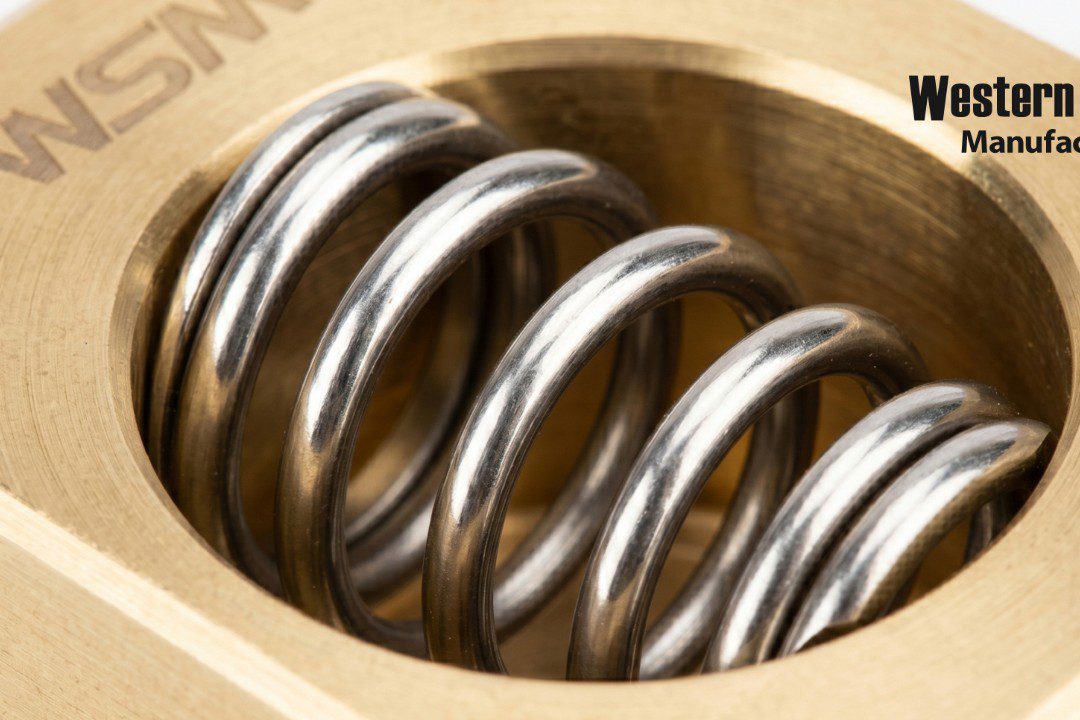
The spring’s inside diameter (ID) is specified nominally smaller than the pin or mandrel it assembles onto. When installed, the coils expand slightly under radial load and grip the pin through contact pressure distributed along the helix. The spring does not slide freely — it is held in axial and rotational position by that grip.
Spring Inside a Bore or Housing
The spring’s outside diameter (OD) is specified nominally larger than the bore it seats in. During installation, the coils compress radially. The resulting spring-back force presses outward against the bore wall, creating the friction that holds the spring in position.
Both configurations share the same underlying mechanic: dimensional interference creates radial deflection in the coil wire, and that deflection generates the contact force responsible for retention.
Real-World Examples
Common Applications of Friction Fit Spring Interfaces
Friction-fit spring interfaces are more common across industries than many engineers expect.
Typical applications include:
- Return springs in valves and actuators that must stay registered to a housing without a secondary retainer.
- Compression springs used in cartridge assemblies where axial retention prevents migration during cycling.
- Torsion springs with legs engaged in holes or slots where slip resistance determines consistent torque delivery.
- Medical coils and precision instrument springs in applications where fasteners and adhesives are prohibited by design constraints or sterilization requirements.
- Automotive and aerospace subassemblies where snap-in retention eliminates secondary operations and speeds assembly.
In each case, the coil body geometry is carrying the retention function. That puts the dimensional specification at the center of the design.
How the Physics Work
The Mechanics of Friction Retention in a Coil Spring
When a spring coil body is pressed over a pin or into a bore, the individual coils deflect radially. For a cylindrical compression spring over a pin, each active coil behaves as a thin curved beam under radial loading. The contact force distributes along the coil helix rather than concentrating at a single point.
The total friction retention force produced by a spring interference fit depends on several interacting factors:
Amount of Interference
The dimensional difference between the spring’s free ID (or OD) and the mating part sets the baseline for how much radial deflection occurs. More interference means more contact force — up to the limits discussed below.
Number of Coils in Contact
More coils engaging the pin or bore produces more cumulative friction. Closed or ground ends may not contribute meaningfully to the contact length, so it’s worth counting only the active or semi-active coils in the friction zone.
Wire Diameter and Coil Index
These govern radial stiffness at the coil level. A spring with a high coil index — large mean diameter relative to wire diameter — is inherently more flexible radially. It will generate less contact force per unit of interference than a tight-wound, low-index spring. Specifying interference without accounting for coil index leads to unpredictable retention behavior across a production run. For a deeper look at how these variables interact, our article on custom spring design specifications is a useful reference.
Material and Surface Finish
The coefficient of friction between the coil wire and mating surface directly affects holding force. Smoother surface finishes, coatings like PTFE or zinc, and material pairings like stainless-on-stainless all affect the friction coefficient and need to be accounted for in retention calculations.
Pitch and Wind Direction
These variables determine whether grip tightens or loosens when the spring experiences operational torque or axial loading. This is particularly relevant for torsion spring legs in holes or for compression springs in assemblies that see rotational loading.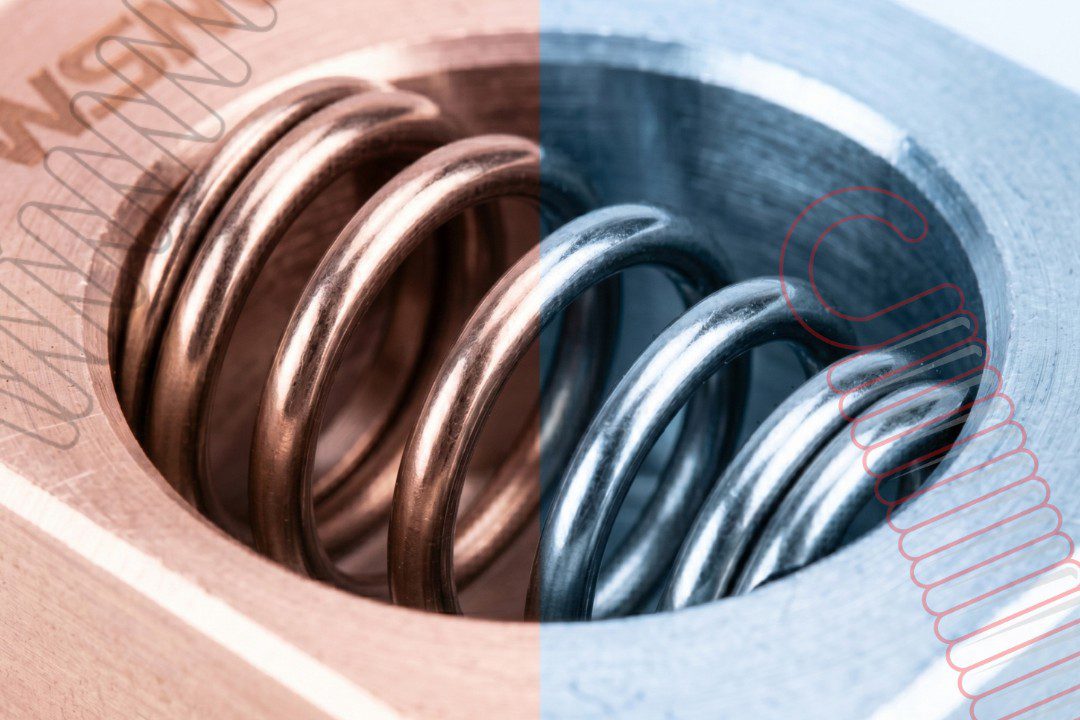
Common Specification Mistakes
Why Over-Interference Creates Problems
The instinct when designing a friction fit spring interface is to specify the most interference possible to guarantee retention. However, that approach creates problems in production.
Assembly Damage
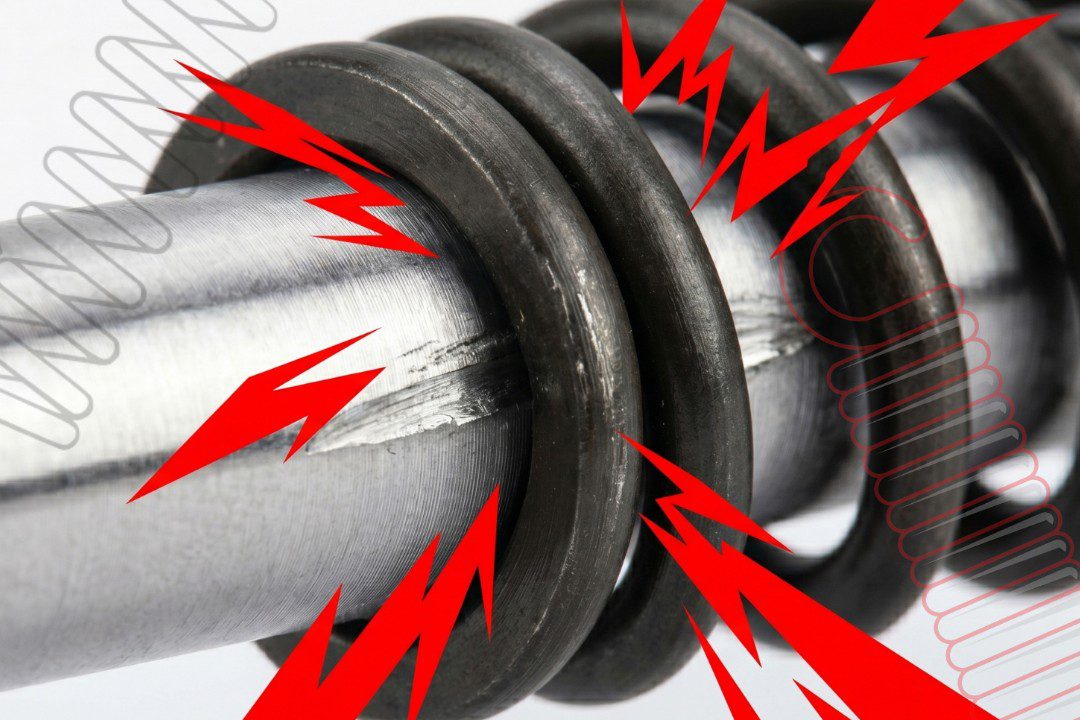
Excessive interference can cause coil-to-coil contact during installation, over-stressing the wire in bending. Surface damage introduced at that moment becomes a fatigue initiation site that shortens service life regardless of how well the spring is designed in every other respect. Our article on preventing spring failure covers how contact damage and stress concentration drive early failures.
Permanent Set in the Coil Body
If the interference exceeds the elastic capacity of the coil cross-section, the coils take a permanent set. The spring loses its ability to exert consistent radial force and may loosen over time, particularly under temperature cycling. A spring that started with too much interference can end up with less retention than one designed to the correct range.
Bore or Pin Damage
Softer housing materials, such as aluminum, plastic, brass, are vulnerable to galling or deformation when spring OD is significantly oversized. This is especially relevant in medical and aerospace assemblies where housing tolerances are tight and housing repair isn’t an option.
Distorted Load-Deflection Behavior
In springs intended to compress or extend axially, excessive radial grip creates friction drag that distorts the load-deflection curve. In these conditions, the spring no longer behaves according to its specified rate under operating conditions.
The practical rule to follow is: friction fit interference should be specified at the minimum level that achieves reliable retention across the full tolerance stack.
Where Designs Get Complicated
Tolerance Stack-Up in Friction Fit Spring Design
This is where spring interference fit design gets complex. A coil spring’s free ID and OD aren’t directly controlled dimensions. They’re outcomes of the coiling process; in other words, products of wire diameter tolerance, mandrel size, spring-back behavior, and coiling machine dynamics.
For a friction fit to function reliably across a full production run, the designer needs to evaluate the complete tolerance stack.
- Spring OD or ID tolerance, which runs ±1–3% of nominal for precision springs.
- Mating bore or pin diameter tolerance.
- Combined worst-case interference at both minimum and maximum material condition.
- Temperature range and differential thermal expansion, particularly when the spring and housing are made from different materials.
A correctly designed friction fit spring interface remains functional, meaning it retains the spring, at minimum interference, and does not over-stress the coil wire or damage the mating part at maximum interference. If the tolerance stack can’t deliver that window, the design needs revision: tighter tolerances, different material, or a mechanical retainer added to the assembly. Our article on go/no-go gauging explains how dimensional verification at the production level catches tolerance problems before they reach assembly.

Choosing the Right Wire Material
Material Selection for Friction Fit Spring Applications
Wire material affects friction fit performance through two properties: elastic modulus, which governs how much radial contact force a given interference generates, and surface condition, which affects the friction coefficient at the mating interface.
Hard-Drawn and Music Wire
- High modulus, consistent surface finish.
- A reliable choice for friction fits against harder steel or aluminum mating parts.
- Widely available and cost-effective for most industrial applications.
Stainless Steel (302/304)
- Slightly lower modulus than carbon steel.
- The smoother surface finish common on stainless wire often produces a lower friction coefficient, which needs to be factored into retention calculations.
- Stainless-on-stainless interfaces carry a galling risk that should be evaluated when both the spring and housing are stainless.
Our spring material options page provides a useful material comparison.
Phosphor Bronze
- Lower modulus than steel, which means more radial deflection for the same interference but less contact force per unit of interference.
- Good corrosion resistance and better friction behavior against brass or copper alloy housings.
Inconel and Hastelloy
- High modulus with strong radial force generation.
- Useful in aerospace and defense applications where elevated temperature performance is required.
- Galling risk at the interface needs attention, particularly in tight-clearance fits.
- Shot peening increases fatigue life in the contact zone but may reduce surface friction slightly.
- Coatings such as zinc, passivation, and PTFE change the friction coefficient meaningfully and must be included in retention calculations, not treated as incidental.
For a full review of how surface processing affects spring performance, see our article on spring treatments and finishing options.
Coil Geometry and Retention
Closed-Coil vs. Open-Coil Bodies in Friction Fit Applications
Coil pitch has a direct effect on how predictably a spring generates retention force.
Closed-Coil Springs
Zero or near-zero pitch means adjacent coils support each other radially. Contact with the bore or pin wall is more consistent along the engagement length, and the spring is less prone to tilting or localized deflection under radial interference. For friction fits over long engagement lengths, a closed or closely-wound spring body delivers more predictable retention.
Open-Coil Springs
Significant pitch between coils means less mutual radial support. Open-wound springs are more susceptible to tilting and localized coil deflection under radial load. Even when an open-wound spring meets the axial load specification on paper, it may not deliver consistent friction retention in a bore or pin fit.
The selection between the two depends on the full assembly context. If the spring also needs to compress axially in service, an open-coil body may be required for functional reasons, and that trade-off needs to be addressed at the interference specification level.

Before You Finalize Your Design
Pre-Design Checklist: Questions to Answer Before Finalizing a Friction Fit Spring Interface
Working through the following questions before locking in your spring geometry will help you catch the most common sources of friction fit failure.
1. What retention force is required?
Back-calculate from the application: axial force, vibration environment, and assembly acceleration.
2. What is the full tolerance stack at minimum and maximum interference?
Confirm retention at minimum material condition and no over-stress at maximum.
3. How many coils fall in the friction zone?
Closed or ground ends may not contribute. Count only active or semi-active coils engaging the pin or bore.
4. Does grip direction stay consistent in service? Under operational torque or axial load, does the spring tighten its grip or release it? What is the operating temperature range?
Differential thermal expansion between the spring wire and housing can substantially shift effective interference over time.
5. Is installation repeatable?
Automated assembly and hand assembly have different alignment precision. A friction fit requiring precise axial alignment may not be suitable for high-volume production.
6. What is the disassembly requirement?
Permanent retention and serviceable retention are different design targets and may lead to different interference specifications.
If any of these questions reveal a problem in your current specification, now is the time to revise the design. Not after tooling has been cut. Our design assistance team is happy to work through these questions with you before you commit to a print.
How Western Spring Manufacturing Can Help
Working with a Trusted Spring Manufacturer on Friction Fit Design
The best outcomes on friction fit spring interfaces come from early collaboration between the design engineer and the spring manufacturer. A manufacturer with production experience can tell you (before you finalize a drawing) what OD or ID tolerance window is realistically achievable for your wire size, material, and coil count, and what interference range is safe without risking coil damage or inconsistent retention across production lots.
At Western Spring Manufacturing, we work with engineers on fit and retention questions across compression springs, torsion springs, medical coils, and custom wire forms. Getting coil body dimensions right the first time eliminates costly iteration and makes sure your assembly performs as designed from the first production run. Contact our team today to discuss your application.